
Building a wifi based IoT device for home automation
In this blog post, we will build an Internet Of Thing (IoT) device based on the super cheap ESP8266 chip. The device is used to automate home shutters at a predefined time of the day or according to the house temperature in order to limit the temperature increase caused by sunlight. The ESP8266 chip is a microcontroller with WiFi capabilities and a full TCP/IP stack. We can, therefore, have a complete web server and REST API running in it so as an MQTT client that can be used to send commands to the chip from anywhere and also to receive data from the chip. The project was split into phases:
1) Desired capabilities:
The requirements for this device are:
- Cheap: We have ~10 shutters to control so it has to be cheap and for sure cheaper than equivalent commercial devices.
- Grid-Powered: It has to be connected to the power plug as we don't want to change the battery of every single device yearly.
- Small: We want it to be located inside the wall of the house in the cavity behind the manual shutter switch (that we are replacing by this device). The footprint should be around 50x40mm with a depth of less than 25mm.
- Connected: It should onboard a webserver, a WiFi antena, and be capable of acting simultaniously as a wifi station or as an access point.
- Over The Air (OTA) Programming: We should be able to update the software of the device remotely. The device will be hardly accessible once placed in the wall.
- Control: The device should be able to roll-down and to roll-up the shutter. It should therefore be able to open/close 220V highly inductive circuits.
- Easy: It should be easy to build and to program, and it has to be well docummented and widely supported by the community.
2) Designing:
The minimal pieces that we need to put together in order to meet these requirements are:
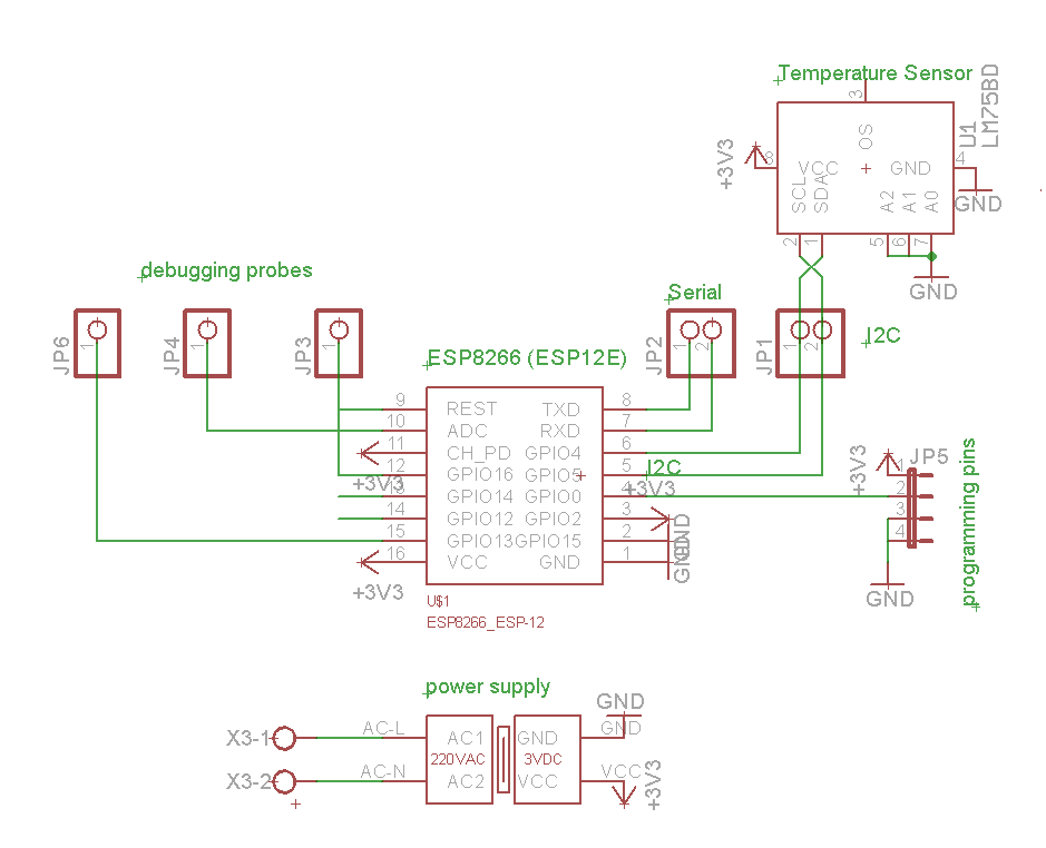
- Connected, Cheap, Easy, Small, and OTA programming: The ESP8266 chip is the ideal candidate for this, it just cost a few dollars, and there are tons of tutorial and documentation all over the web. There are many module version integrating this chip, we opted for the ESP-12E version whih has good WiFi range performance and quite enough GPIO to control our shutters and other stuff like temperature sensors. The ESP8266 module requires a 3.3V power supply delivering 500mA (necessary during WiFi communication).
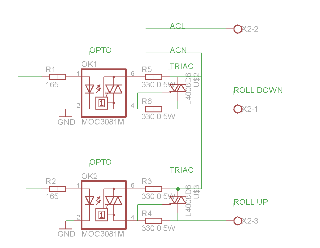
- Conrol and Small: In order to control the shutters we basically have two options, either we use an electrical relay which is cheap but big, noisy, slow and with a limited lifetime or we use (opto-isolated) triacs that are expensive but have the advantage to be small, silent and robust. We chose to use the L4008D6 triacs which can handle 8 Amps in 400VAC and are snubberless which is quite necessary given the high inductance of the shutter motors. The two triacs are controlled by two MOC3081M optocouplers which also add an insulation between the high voltage (220V AC) circuit and the low voltage (3.3V DC) circuit.
- Grid-Powered, Cheap and Small: We need a small footprint power supply that can delive the 3.3VDC required by the ESP8266 from the 220VAC wall plug. Usual passive transformers are excluded has those beast are rather big and expensive. So the only real alternative here are the "made in china" switching power supply that are quite often used in mobile phone chargers. Note that these devices should be used with a lot of care as they handle pretty high voltages (>KV) and load some large capacitors... this is quite a deadly mix so it should really be manipulated with caution.
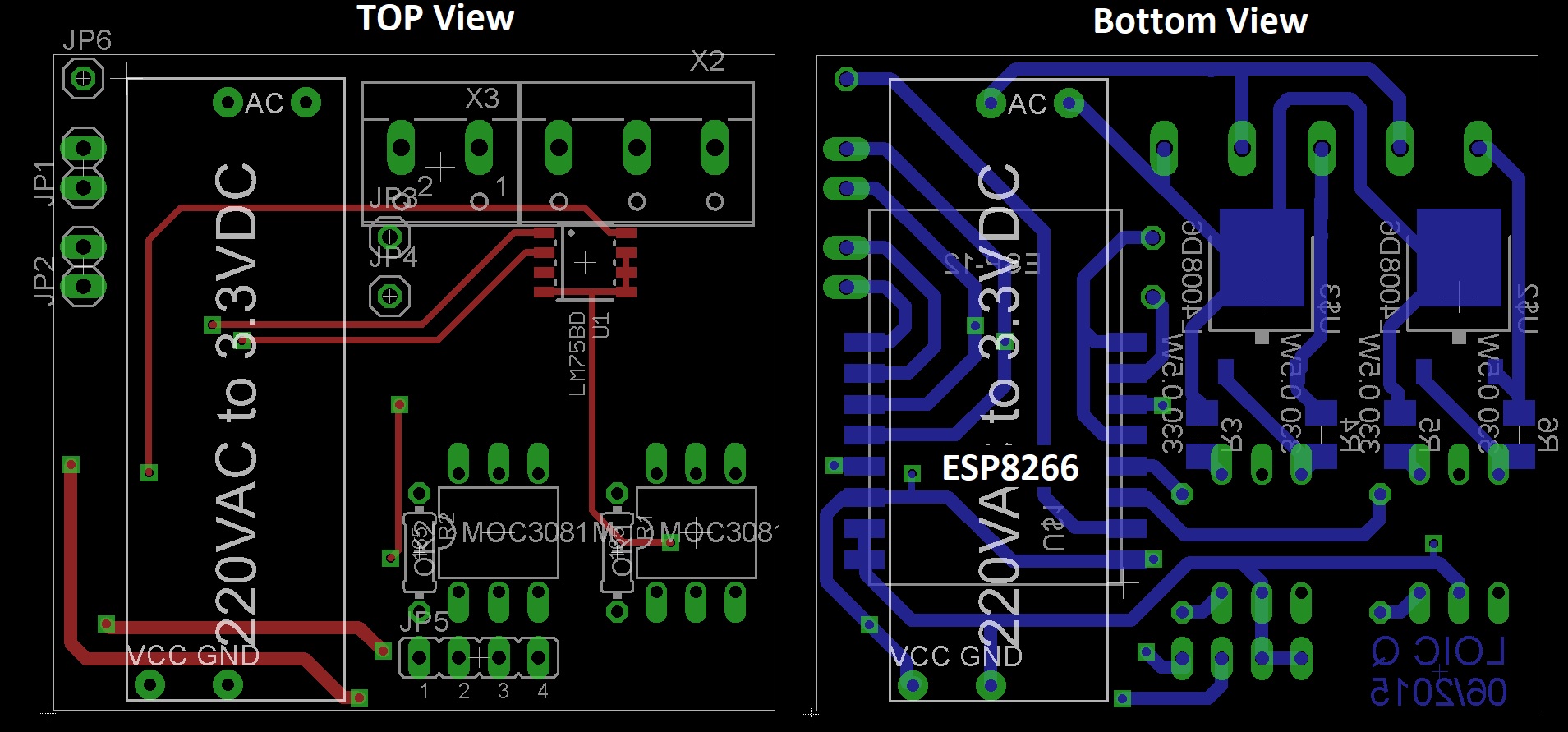
In order to minimize the size of the entire device, we have no other choice than smartly designing the Printed Circuit Board (PCB) of the device to combine all these elements on a minimal space. Note: our final design uses a double sided PCB which have the switching power supply located behind the ESP8266 wifi antena. This is far from idea has the switching power supply could cause interferences that negatively affect the wifi antena. We will therefore need to make an initial prototype to make sure that this location is acceptable. We have also added a small temperature sensor on the board to monitor the Triacs temperature in the testing phase of the board. Note that the proximity of the temperature sensor to the power supply makes it totally unusable to measure the house temperature (there is an obvious bias of 4-5°C).
See below the schema for this device:
See below the board design for this device:
We can now compute what would be the cost of the device based on the component list and price for small quantities:
| Component | Unit Price ($) | Quantity | Total Price ($) |
|---|---|---|---|
| ESP8266_ESP12E | 2.40 | 1 | 2.40 |
| Power-Supply 110V/220V to 3.3V 700mA AC-DC | 1.47 | 1 | 1.47 |
| OptoCoupler MOC3081 | 0.88 | 2 | 1.76 |
| Triac L4008D6 or T405-600B | 0.90 | 2 | 1.80 |
| Resistance RC1206JR-07330RL | 0.01 | 4 | 0.04 |
| Resistance OM16G5E-R58 | 0.06 | 2 | 0.12 |
| Temperature Sensor: | 0.51 | 1 | 0.51 |
| Connector ATB612-508-2P | 0.08 | 1 | 0.08 |
| Connector ATB612-508-3P | 0.08 | 1 | 0.08 |
| pin header 1x8 | 0.02 | 1 | 0.02 |
| double sided PCB (from firstPCB) | 1.84 | 1 | 1.84 |
| TOTAL | 10.12 |
So basically, we are at the level of 10$ per device. The cheapest commercial device I found on the web was around 50$, and they were not as complete as these. Note that there is still some soldering to be done to put all these together... so we are not completely comparing apple to apple. Note however that manual shutter switches already cost more than 10$.
3) From prototyping to production:
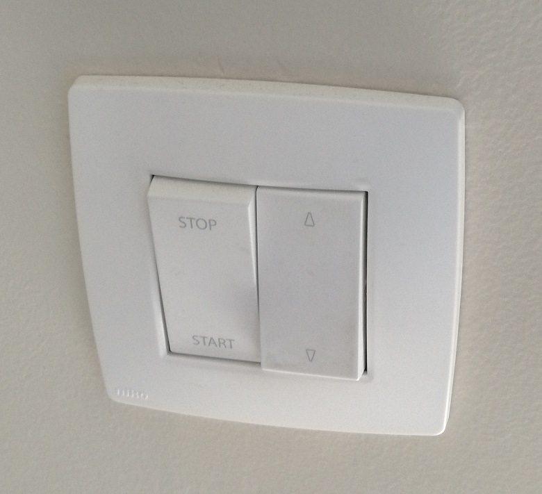
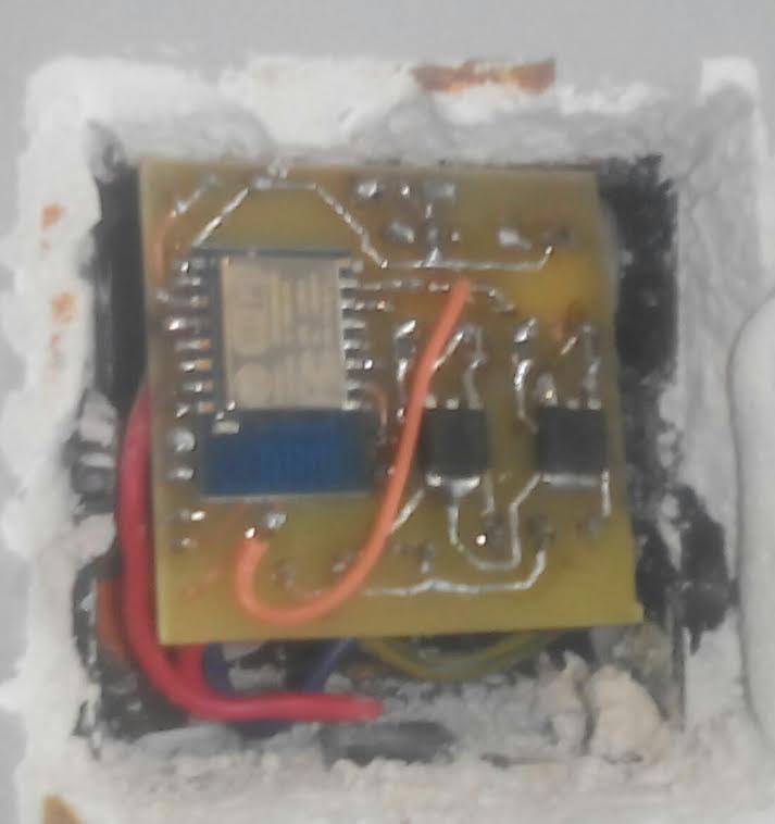
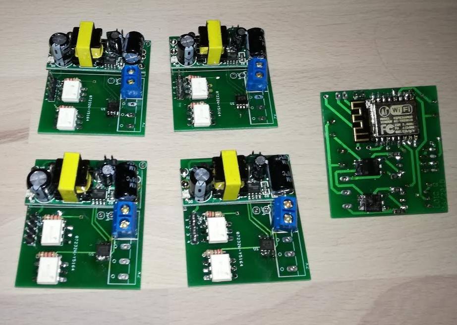
Before ordering all the components and making a PCB order in china (which usualy take a month), let's make a prototyping board on a home-made PCB. The manual shutter switch (first figure) was removed and replaced by the prototype that was inserted into the wall (seecond figure). Note that I am not able to make double sided PCB at home which explains why they are some wires here and there on the prototype. The prototype stayied in place for an entire week which also allowed me to make progress on the software (see next chapter). As I haven't observed any issue regarding WiFi connectivity during the testing period I move forward with the production of 10 devices (last figure).
4) Software Development:
One of the major advantage of the ESP8266 chip is that it is compatible with the Arduino software stack that is widely adopted by the hacker community world wide. There are therefore already many librariries available to do practically anything. See the ESP8266 Arduino github for a complete documentation. So here the software part is mostly reduced to just combinning all the libraries together. I won't go in to the details of my code, but instead, I will list the functionnality that I have implemented in the software.
- The device is visible as a WiFi (password protected) access point to which we can connect to define login/password of the home wifi network (so the chip can connect itself as a station to the home wifi). We can also use this mode to rename the device and set the MQTT Broker address, port and credentials.
- The device connects as a station to the home wifi and stay connected. The device also runs a SSDP and mDNS servers which allows the network to discover the device and get it's hostname and other details => that typically allows windows to properly list the device in the network center and provide easy access to the device web interface from windows.
- The device run a webserver with a list of endpoints to
- Retrieve onboard temperature
- Roll-up / Roll-Down / Stop / Tilt the shutter controlled by the device
- Retrieve device uptime
- Retrieve hardware and software details (software version, MAC address, IP address, device name, connected clients to the device access point, etc.)
- Interact with an external I2C device (that can be connected to the device thanks to connector JP1)
- Set MQTT Broker address, port and credentials
- Update a new firmware via Over The Air programming
- Reboot the device
- ...
- The device run a MQTT client which basically give the same functionnality than the webserver. The client listen on the topic < DEVICE_NAME >/in and publishes to the topic < DEVICE_NAME >/out/log, where basically every action are pushed so we can easilly monitor a fleet of devices from our favorite message broker (i.e. mosquitto). We can also imagine adding other publishing topics for instance to push temperatue measurements every 5 minutes.
- In case of WiFi disconnection, the device wait a bit and then try to reconnect.
5) Central Server:
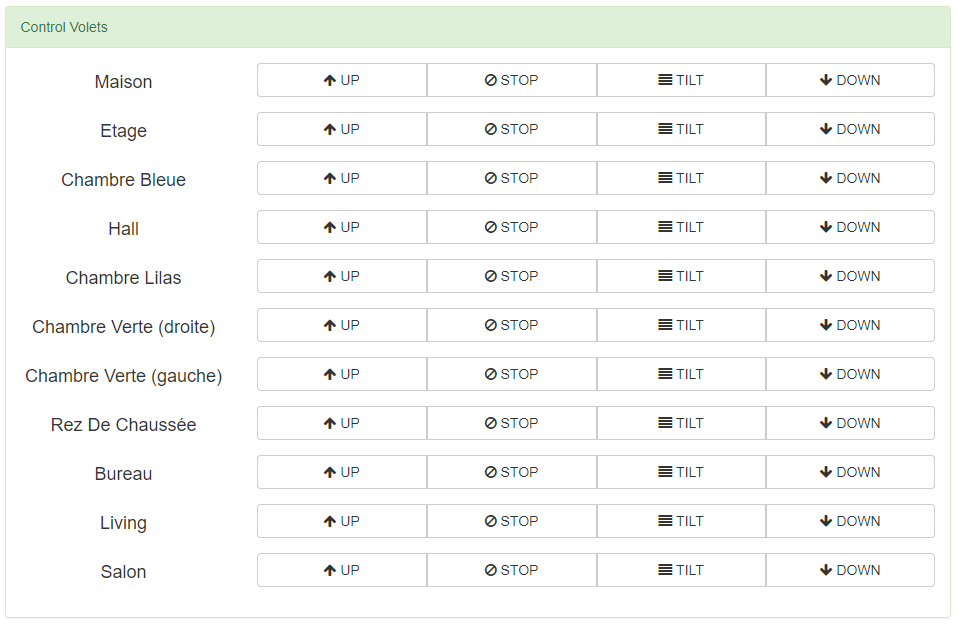
Finally, we need one more piece to orchestrate all the devices at once from a nice user interface. This last piece is a small server that can host the MQTT broker and server as a bridge between the user and the devices. For this, we have used an old raspberry pi on which we have installed the mosquitto MQTT broker and on which we have also deployed a small django website from which we can roll the shutters up and down individuall or all at once. In addition, the django server also run a cron scheduler which automatically roll the shutters up in the morning and down in the evening. More complex logic can also be implemented in there to take actions according to special conditions liek temperature, vacation, etc. This sever is also used as an insulation layer between the wide internet and the secured local network. See the figure bellow to see how this small user interface looks like:
Conclusion:
We have conducted an entire IoT project from A to Z satisfying a specific list of constrains. We've designed the electronic shema for the device, built a prototype, made a small production of final devices, develop their software, setup a server to communicate with these devices using either REST API or MQTT and finally, we have built a simple but handy user interface to orchestrate all these devices.
Have you already faced similar type of issues ?
Feel free to contact us, we'd love talking to you…Don't forget to like and share if you found this helpful!